

Grove – Thumb Joystick
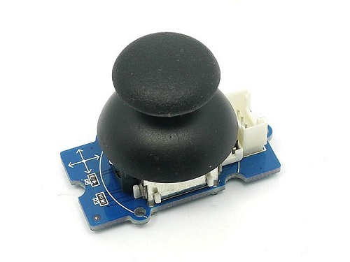
Grove – Thumb Joystick is a Grove compatible module which is very similar to the ‘analog’ joystick on PS2 (PlayStation 2) controllers. The X and Y axes are two ~10k potentiometers which control 2D movement by generating analog signals. The joystick also has a push button that could be used for special applications. When the module is in working mode, it will output two analog values, representing two directions. Compared to a normal joystick, its output values are restricted to a smaller range (i.e. 200~800), only when being pressed that the X value will be set to 1023 and the MCU can detect the action of pressing.
![]()
Version
| Product Version | Changes | Released Date |
|---|---|---|
| Grove – Thumb Joystick V1.1 | Initial | Oct 2016 |
Specifications
| Item | Min | Typical | Max | Unit |
|---|---|---|---|---|
| Working Voltage | 4.75 | 5.0 | 5.25 | V |
| Output Analog Value (X coordinate) | 206 | 516 | 798 | \ |
| Output Analog Value (Y coordinate) | 203 | 507 | 797 | \ |
Tip
More details about Grove modules please refer to Grove System
Platforms Supported
| Arduino | Raspberry Pi | BeagleBone | Wio | LinkIt ONE |
|---|---|---|---|---|
Caution
The platforms mentioned above as supported is/are an indication of the module’s software or theoritical compatibility. We only provide software library or code examples for Arduino platform in most cases. It is not possible to provide software library / demo code for all possible MCU platforms. Hence, users have to write their own software library.
Getting Started
Note
If this is the first time you work with Arduino, we firmly recommend you to see Getting Started with Arduino before the start.
Play With Arduino
Demonstration
The Grove – Thumb Joystick is an analog device that outputs analog signal ranging from 0 to 1023. That requires us to use the analog port of Arduino to take the readings.
Hardware
- Step 1. Prepare the below stuffs:
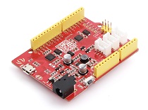
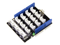
| Seeeduino V4.2 | Base Shield | Grove – Thumb Joystick |
|---|---|---|
 |
 |
 |
| Get One Now | Get One Now | Get One Now |
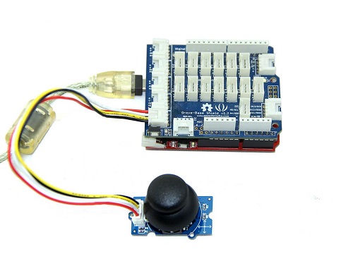
- Step 2. Connect the module to the A0/A1 of Grove – Base Shieldby using the 4-pin grove cable.
- Step 3. Plug Grove – Base Shield into Seeeduino.
- Step 4. Connect Seeeduino to PC via a USB cable.
Note
If we don’t have Grove Base Shield, We also can directly connect Grove-Thumb Joystick to Seeeduino as below.
| Seeeduino | Grove – Thumb Joystick |
|---|---|
| 5V | Red |
| GND | Black |
| A1 | White |
| A0 | Yellow |
Software
- Step 1. Copy and paste code below to a new Arduino sketch.
1 2 3 4 5 6 7 8 9 10 11 12 13 14 15 16 17 18 19 20 21 22 23 |
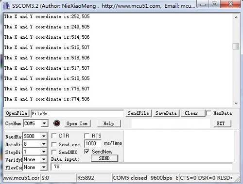
/* Thumb Joystick demo v1.0 by:http://www.seeedstudio.com connect the module to A0&A1 for using; */ void setup() { Serial.begin(9600); } void loop() { int sensorValue1 = analogRead(A0); int sensorValue2 = analogRead(A1); Serial.print("The X and Y coordinate is:"); Serial.print(sensorValue1, DEC); Serial.print(","); Serial.println(sensorValue2, DEC); Serial.println(" "); delay(200); } |
- Step 2. You can check the values of the output analog signals by opening the Serial Monitor.
The output value from the analog port of Arduino can be converted to the corresponding resistance by using the formula:R=(float)(1023-sensorValue)*10/sensorValue.
Play with Codecraft
Hardware
Step 1. Connect a Grove – Thumb Joystick to port A0 of a Base Shield.
Step 2. Plug the Base Shield to your Seeeduino/Arduino.
Step 3. Link Seeeduino/Arduino to your PC via an USB cable.
Software
Step 1. Open Codecraft, add Arduino support, and drag a main procedure to working area.
Note
If this is your first time using Codecraft, see also Guide for Codecraft using Arduino.
Step 2. Drag blocks as picture below or open the cdc file which can be downloaded at the end of this page.
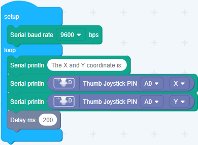
Upload the program to your Arduino/Seeeduino.
Success
When the code finishes uploaded, you will see the coordinate of X and Y displayed in the Serial Monitor.
Play With Raspberry Pi (With Grove Base Hat for Raspberry Pi)
Hardware
- Step 1. Things used in this project:
| Raspberry pi | Grove Base Hat for RasPi | Grove – Thumb Joystick |
|---|---|---|
 |
 |
|
| Get ONE Now | Get ONE Now | Get ONE Now |
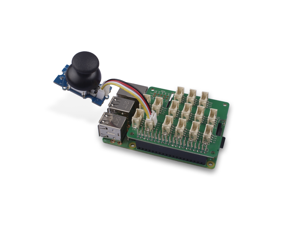
- Step 2. Plug the Grove Base Hat into Raspberry.
- Step 3. Connect the Thumb Joystick to port A0 of the Base Hat.
- Step 4. Connect the Raspberry Pi to PC through USB cable.
Note
For step 3 you are able to connect the the thumb joystick to any Analog Port but make sure you change the command with the corresponding port number.
Software
- Step 1. Follow Setting Software to configure the development environment.
- Step 2. Download the source file by cloning the grove.py library.
1 2 |
cd ~ git clone https://github.com/Seeed-Studio/grove.py |
- Step 3. Excute below commands to run the code.
Note
you can excute the program with ++python grove_thumb_joystick.py pin++, where pin could be one of {0, 2, 4, 6} in the ADC group and connect the device to the corresponding slot {A0, A2, A4, A6}.
Following is the grove_thumb_joystick.py code.
1 2 3 4 5 6 7 8 9 10 11 12 13 14 15 16 17 18 19 20 21 22 23 24 25 26 27 28 29 30 31 32 33 34 35 36 |
import math import sys import time from grove.adc import ADC class GroveThumbJoystick: def __init__(self, channelX, channelY): self.channelX = channelX self.channelY = channelY self.adc = ADC() @property def value(self): return self.adc.read(self.channelX), self.adc.read(self.channelY) Grove = GroveThumbJoystick def main(): from grove.helper import SlotHelper sh = SlotHelper(SlotHelper.ADC) pin = sh.argv2pin() sensor = GroveThumbJoystick(int(pin), int(pin + 1)) while True: x, y = sensor.value if x > 900: print('Joystick Pressed') print("X, Y = {0} {1}".format(x, y)) time.sleep(.2) if __name__ == '__main__': main() |
Success
If everything goes well, you will be able to see the following result
1 2 3 4 5 6 7 8 9 10 11 12 13 14 15 16 17 18 19 20 21 22 23 24 25 |
pi@raspberrypi:~/grove.py/grove $ python grove_thumb_joystick.py 0 Hat Name = 'Grove Base Hat RPi' X, Y = 506 484 X, Y = 484 484 X, Y = 506 484 X, Y = 506 487 Joystick Pressed X, Y = 999 485 X, Y = 310 736 X, Y = 681 484 Joystick Pressed X, Y = 999 277 Joystick Pressed X, Y = 999 487 X, Y = 506 484 X, Y = 501 486 X, Y = 509 484 X, Y = 511 486 X, Y = 510 485 ^CTraceback (most recent call last): File "grove_thumb_joystick.py", line 69, in <module> main() File "grove_thumb_joystick.py", line 66, in main time.sleep(.2) KeyboardInterrupt |
You can quit this program by simply press Ctrl+C.
Notice
You may have noticed that for the analog port, the silkscreen pin number is something like A1, A0, however in the command we use parameter 0 and 1, just the same as digital port. So please make sure you plug the module into the correct port, otherwise there may be pin conflicts.
Play With Raspberry Pi (with GrovePi_Plus)
Hardware
- Step 1. Prepare the below stuffs:
| Raspberry pi | GrovePi_Plus | Grove – Thumb Joystick |
|---|---|---|
|
 |
|
| Get One Now | Get One Now | Get One Now |
- Step 2. Plug the GrovePi_Plus into Raspberry.
- Step 3. Connect Grove-Thumb Joystick ranger to A0 port of GrovePi_Plus.
- Step 4. Connect the Raspberry to PC through USB cable.

Software
- Step 1. Navigate to the demos’ directory:
1 |
cd yourpath/GrovePi/Software/Python/ |
- Step 2. To see the code
1 |
nano grove_thumb_joystick.py # "Ctrl+x" to exit # |
1 2 3 4 5 6 7 8 9 10 11 12 13 14 15 16 17 18 19 20 21 22 23 24 25 26 27 28 29 30 31 32 33 34 35 36 37 38 39 40 41 42 43 44 45 46 47 48 49 50 51 52 53 |
import time import grovepi # Connect the Grove Thumb Joystick to analog port A0 # GrovePi Port A0 uses Arduino pins 0 and 1 # GrovePi Port A1 uses Arduino pins 1 and 2 # Don't plug anything into port A1 that uses pin 1 # Most Grove sensors only use 3 of their 4 pins, which is why the GrovePi shares Arduino pins between adjacent ports # If the sensor has a pin definition SIG,NC,VCC,GND, the second (white) pin is not connected to anything # If you wish to connect two joysticks, use ports A0 and A2 (skip A1) # Uses two pins - one for the X axis and one for the Y axis # This configuration means you are using port A0 xPin = 0 yPin = 1 grovepi.pinMode(xPin,"INPUT") grovepi.pinMode(yPin,"INPUT") # The Grove Thumb Joystick is an analog device that outputs analog signal ranging from 0 to 1023 # The X and Y axes are two ~10k potentiometers and a momentary push button which shorts the x axis # My joystick produces slightly different results to the specifications found on the url above # I've listed both here: # Specifications # Min Typ Max Click # X 206 516 798 1023 # Y 203 507 797 # My Joystick # Min Typ Max Click # X 253 513 766 1020-1023 # Y 250 505 769 while True: try: # Get X/Y coordinates x = grovepi.analogRead(xPin) y = grovepi.analogRead(yPin) # Calculate X/Y resistance Rx = (float)(1023 - x) * 10 / x Ry = (float)(1023 - y) * 10 / y # Was a click detected on the X axis? click = 1 if x >= 1020 else 0 print "x =", x, " y =", y, " Rx =", Rx, " Ry =", Ry, " click =", click time.sleep(.5) except IOError: print "Error" |
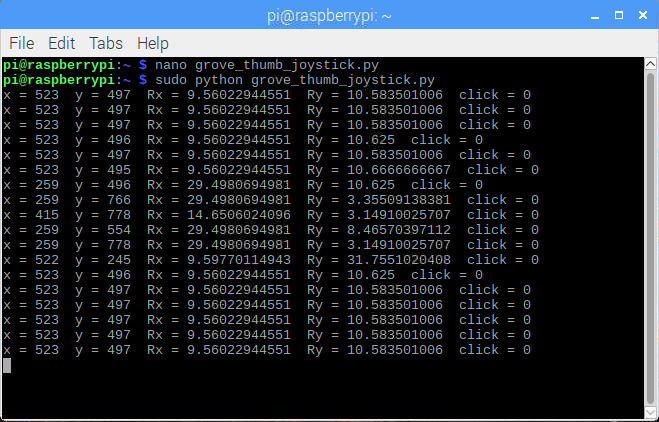
- Step 3. Run the demo.
1 |
sudo python grove_thumb_joystick.py |
- Step 4. We will see the output display on terminal as below.
 |
|
Resources
- [Eagle] Grove-Thumb Joystick Schematic
- [Datasheet] Analog Joystick Datasheet
- [PDF] Joystick Schematic PDF File
- [Codecraft] CDC File
Projects
Raspberry pi music server: A first step to Raspberry Pi project.
Build a Custom Minecraft Controller: Build a Custom Minecraft Controller With the GrovePi.
Tech Support
Please submit any technical issue into our forum.

Analog 2-axis Thumb Joystick with Select Button + Breakout Board
DESCRIPTION
The thumbstick is an analog joystick – more accurate and sensitive than just ‘directional’ joysticks – with a ‘press in to select’ button. Since it’s analog, you’ll need two analog reading pins on your microcontroller to determine X and Y. Having an extra digital input will let you read the switch.
The pack comes in three parts – the joystick itself, a soft-touch rubber ‘hat’ and a nicely designed breakout board. We designed the breakout so that you can attach the joystick to a panel easily – every other breakout we wanted to carry had the mounting holes so they were in the way of the joystick movement! A 5 pin 0.1″ spaced header makes it easy to connect either in a perfboard/breadboard setting or free wiring. You’ll need to solder the joystick into the PCB using a soldering iron and solder, but its very simple and will only take a minute.


Categories: Uncategorized
